
Design and Implementation of Different Arithmetic Circuits
Theory
1. Binary Adder - Subtractor
Digital computers perform variety of information tasks. Among the functions encountered are the various arithmetic operations. The most basic arithmetic operation is the addition of two binary digits. This simple addition consists of four possible elementary operations. 0 + 0 = 0, 0 + 1 = 1, 1 + 0 = 1, 1 + 1 = 10. The first three operations produce sum of one digit, but when the both augends and addend bits are equal 1, the binary sum consists of two digits. The higher significant bit of the result is called carry .When the augend and addend number contains more significant digits, the carry obtained from the addition of the two bits is called half adder. One that performs the addition of three bits (two significant bits and a previous carry) is called half adder. The name of circuits from the fact that two half adders can be employed to implement a full adder.
A binary adder-subtractor is a combinational circuit that performs the arithmetic operations of addition and subtraction with binary numbers. We will develop this circuit by means of a hierarchical design. The half adder design is carried out first, from which we develop the adder. Connecting n full adders in cascade produces a binary adder for two n-bit numbers.
The subtraction circuit is included by providing a complementing circuit.
1.1 Half Adder
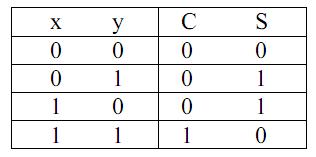
From the verbal explanation of a half adder, we find that this circuit needs two binary inputs and two binary outputs. The input variables designated the augend and addend bits; the output variables produce the sum and carry. We assign symbols x and y to the inputs and S (for sum) and C (for carry) to the outputs. The truth table for the half adder is listed in Table 1. The C output is 1 only when both inputs are 1. The S output represents the least significant bit of the sum.
The simplified Boolean functions for the two outputs can be obtained directly from the truth table. The simplified sum of products expressions are:

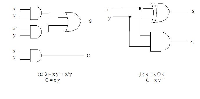
The logic diagram of the half adder implemented in sum of product is shown in fig. 1(a). It can be also implemented with an exclusive-OR and AND gate as shown in fig. 1(b). This form is used to show that two half adders can be used to construct a full adder.
Equations:
1.2 Full-adder
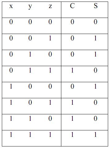
A full adder is a combinational circuit that forms the arithmetic sum of three bits. It consists of three inputs and two outputs. Two of the inputs variables, denoted by x and y, represent the two significant bits to be added. The third input, z, represents the carry from the previous lower significant position. Two outputs are necessary because the arithmetic sum of three binary digits ranges in value from 0 to 3, and binary 2 or 3 needs two digits. The two outputs are designated by the symbols S for sum and C for carry. The binary variable S gives the value of the least significant bit of the sum. The binary variable C gives the output carry. The truth table of the full adder is listed in table 2. The eight row under the input variables designate all possible combinations of the three variables. The output variables are determined from the arithmetic sum of the input bits. When all input bits are 0, the output is 0. The S output is equal to 1 when only one input is equal to 1 or when all three inputs are equal to 1. The C output has a carry of 1 if two or three inputs are equal to 1.
A input and output bits of the combinational circuit have different interpretations at various stages of the problem. Physically, the binary signals of the inputs are considered binary digits to be added arithmetically to form a two-digit sum at output. On the other hand, the binary values are considered as variables of Boolean functions when expressed in the truth table or when the circuit is implemented with logic gates.
The simplified expressions are: S = x' y' z + x' y z' + x y' z' + xyz C = x y + x z + y z
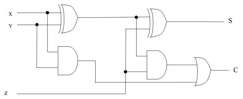
It can be also implemented with two half adders and OR gate. As shown in fig 2.The S output from the second half adder is the exclusive-OR of z and the output of the first half adder, giving
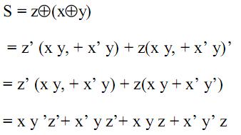
The carry output is C= z (x y' + x' y) + x y = x y' z + x' y z + x y
1.3 Binary Adder
A binary adder is a digital circuit that produces the arithmetic sum of two binary numbers. It can be constructed with full adder connected in cascade, the output carry from each full adder connected to the input carry of the next full adder in the chain. Fig 3 shows the interconnection of four full adder (FA) circuits to provide a 4-bit binary ripple carry adder. The augend bits of A and addend bits of B are designated by subscript numbers from right to left , with subscript 0denoting the least significant bit. The carries are connected in the chain through the full adders. The input carry to the adder is C0 and it ripples through the full adder to the output carry C4.The S output generate the required sum bits. An n-bit adder requires n full adders with each output connected to the input carry of the next higher order full adder.
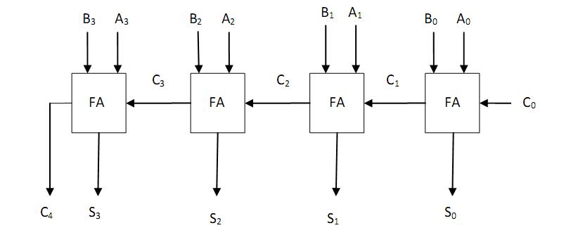
The bits are added with full adders, starting from the position to form the sum bit and carry. The input carry C0 in the least significant position must be 0. The value of Ci+1 in a given significant position is the output carry of the full adder. This value is transferred into the input carry of the full adder that adds the bits one higher significant position to the left. The sum bits are thus generated starting from the rightmost position and are available for the correct sum bits to appears at the outputs.
The 4bit adder is a typical example of a standard component. It can be used in many applications involving arithmetic operations. Observe that the design of this circuit by the classical method would require a truth table with 29 = 512 entries, since there are nine inputs to the circuit. By using an iterative method of cascading a standard function, it is possible to obtain a simple and straightforward implementation.
1.4 Binary Subtractor
The subtraction of unsigned binary numbers can be done most conveniently by means of complement. Subtraction A–B can be done by tacking the 2's complement of B and adding it to A. The 2's complement can be obtained by taking the 1's complement and adding one to the least significant pair of bits. The 1's complement can be implemented with the inverters and a one can be added to the sum through the input carry. The circuit for subtracting A–B consists of an adder with inverter placed between each data input B and the corresponding input of the full adder. The input carry C0 must be equal to 1 when performing subtraction. The operation thus performed becomes A, plus the 1's complement of B, plus 1.This is equal to A plus 2's complement of B. For unsigned numbers this gives A–B if A = B or the 2's complement of (B–A) if A < B. for signed numbers, the result is A – B, provided that there is no overflow.
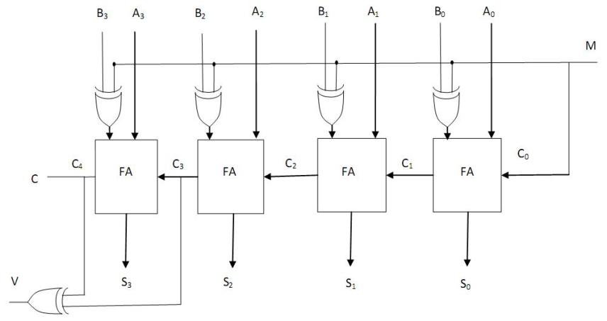
The addition and subtraction operations can be combined into one circuit with one common binary adder. This is done by including an EX-OR gate with each full adder. A 4-bit adder-subtractor circuit is shown in fig 4. The mode input M controls the operation. When M = 0, the circuit is an adder, and when M = 1, the circuit becomes a subtractor. Each EX-OR gate receives input M and one of the inputs of B. when M = 0, we have B (Ex-OR) 0 = B. the full adder receive the value of B, the input carry is 0, and the circuit performs A plus B. when M = 1, we have B (Ex-OR) 1= B' and C0 = 1. The B inputs are complemented and a 1 is added through the input carry. The circuit performs the operation A plus the 2's complement of B. (The EX-OR with output is for detecting an overflow.)
It is worth noting that binary numbers in the signed-complemented system are added and subtracted by the same basic addition and subtraction rules as unsigned numbers. Therefore, computers need only one common hardware circuit to handle both type of arithmetic. The user or programmer must interpret the results of such addition or subtraction differently. Depending on whether it is assumed that the numbers are signed or unsigned.
1.5 Overflow
When two numbers of n digits are added and the sum occupies n + 1 digits, we say that an overflow occurred. This is true for binary or decimal numbers whether signed or unsigned. When the addition is performed with paper and pencil, an overflow is not a problem, since there is no limit by the width of the page to write down the sum. Overflow is a problem in digital computers because the number of bits that hold the number is finite and a result that contains n + 1 not be accommodated. For this reason, many computers detect the occurrence of an overflow and when it occurs, a corresponding flip-flop is set that can then be checked by the user.
The detection of an overflow after the addition of two binary numbers depends on the numbers are considered to be signed or unsigned. When two unsigned numbers are an overflow is detected from the end carry out of the most significant position. In the signed numbers, the leftmost bit always represents the sign and negative numbers are in 2's complement form. When two signed numbers are added, the sign bit is treated as part of the number and the end carry does not indicate an overflow.
An overflow cannot occur after an addition if one number is positive and the other is negative, since adding a positive number to a negative number produces a result which is than the larger of the two original numbers. An overflow may occur if the two numbers are both positive and both negative. To see how this can happen, consider the following example. Two signed binary numbers, +70 and +80, are stored in two 8-bit registers. The range of numbers that each register can accommodate is from binary + 127 to binary -128. Since sum of the two numbers is + 150, it exceeds the capacity of an 8-bit register. This is true if numbers are both positive or both negative. The two additions in binary are shown next, together with the last two carries;
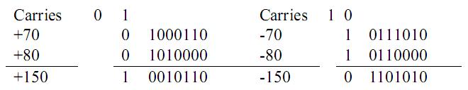
Note that the 8-bit result that should have been positive has a negative sign bit and the 8-bit that should have been negative has a positive sign bit. If, however, the carry out of the sign bit position is taken as the sign bit of the result, then the 9-bit answer so obtained will be correct. Since the answer cannot be accommodated within 8-bits, we say that an overflow has occurred. An overflow condition can be detected by observing the carry into the sign bit position and the carry out of the sign bit position. If these two carries are not equal, an overflow has occurred.
This is indicated in the examples where the two carries are explicitly shown. If the two carries are applied to an exclusive-OR gate, an overflow is detected when the output of the gate equal to 1. For this method to work correctly the 2's complement must be computed by taking the 1 's complement and adding one. This takes care of the condition when the maximum negative number is complemented.
The binary adder- subtractor circuit with outputs C and V as shown in fig 6. If the two binary numbers are considered to be unsigned, then the C bit detects a carry after addition or a borrow after subtraction. If the numbers are considered to be signed, then the V bit detects an overflow. If V = 0 after an addition or subtraction, it indicates that no overflow occurred and the n-bit result is correct. If V = 1, then the result of the operation contains n + 1 bits, but only the rightmost n bits of the number fit in the space available, so an overflow has occurred. The (n + 1) th bit is the actual sign and has been shifted out of position.