
Implementation of monostable and astable oscillator using IC 555
Theory
Introduction
Applications such as oscillators, pulse generators, ramp or square wave generators, multivibrators require a circuit capable of timing intervals. The most popular circuit is the 555 timer. The IC is consisting of combinations of linear comparators and digital flip flops. The IC 555 is reliable and easy to use for various applications. The entire IC is housed in eight pin package. The IC can operate from 5 to 18 V. The timer IC 555 consist of two transistors, two comparators, three equal resistors, flip flop and output stage. A series connection of three equal resistors sets the reference voltage level of the two comparators at 2VCC/3 and VCC/3 the output of these comparators setting or resetting the flip/flop unit. The IC timer 555 has two operational modes, monostable or astable multivibrator. The IC 555 available in two packages DIP and TO99.
Pin Description of IC555 Timer
pin1. - Ground, The ground pin connects the 555 timer to the negative (0v) supply rail.
Pin2. - Trigger, The negative input to comparator No 1. A negative pulse on this pin "sets" the internal Flip-flop when the voltage drops below 1/3Vcc causing the output to switch from a "LOW" to a "HIGH" state.
Pin3. - Output, The output pin can drive any TTL circuit and is capable of sourcing or sinking up to 200mA of current at an output voltage equal to approximately Vcc - 1.5V so small speakers, LEDs or motors can be connected directly to the output.
Pin4. - Reset, This pin is used to "reset" the internal Flip-flop controlling the state of the output, pin 3. This is an active-low input and is generally connected to a logic "1" level when not used to prevent any unwanted resetting of the output.
Pin5. - Control Voltage, This pin controls the timing of the 555 by overriding the 2/3Vcc level of the voltage divider network. By applying a voltage to this pin the width of the output signal can be varied independently of the RC timing network. When not used it is connected to ground via a 10nF capacitor to eliminate any noise.
Pin6. - Threshold, The positive input to comparator No 2. This pin is used to reset the Flip-flop when the voltage applied to it exceeds 2/3Vcc causing the output to switch from "HIGH" to "LOW" state. This pin connects directly to the RC timing circuit.
Pin7. - Discharge, The discharge pin is connected directly to the Collector of an internal NPN transistor which is used to "discharge" the timing capacitor to ground when the output at pin 3 switches "LOW".
Pin8. - Supply +Vcc, This is the power supply
Astable Operation:
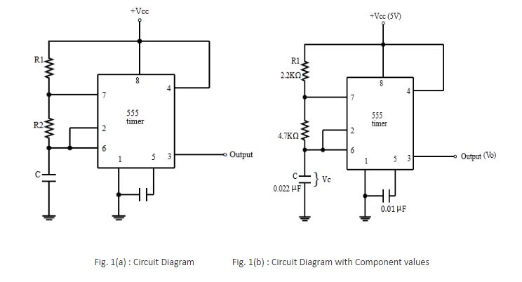
One popular application of IC 555 is astable multivibrator. Fig. 1 shows astable circuit constructed using the external resistors and capacitor to set the timing of the output signal. The capacitor charges through resistors R1 and R2 the voltages across capacitor rises to 2VCC/3. This voltage acts as a threshold voltage at pin 6 which is input to internal comparator which finally trigger the internal flip flop so that output pin goes low. Also flip flop drives the internal discharge transistor to ON allowing capacitor to get discharge from R2 this lead to decrease in capacitor voltage to VCC/3 and the flip flop get trigger and discharge transistors gets off and output set to high. This leads to charging of capacitor through R1 and R2 to VCC.
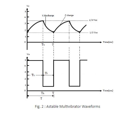
The fig. 2 shows the waveforms associated with astable multivibrator. The calculation for the timing related to low and high output is given by The calculation for low and high has been as per the following equations
TH = 0.7(R1 +R2)C TL = 0.7R2C
The total time T is given as,
T = TH + TL
The equation for total time interval T is given as
T = (R1 + 2R2)C/1.44
For the given values R1 = 2.2KΩ, R2 = 4.7 KΩ and C= 0.022μF, frequency of operation will be 5.64 KHz and duty cycle will be 59.5%
Monostable Operation:
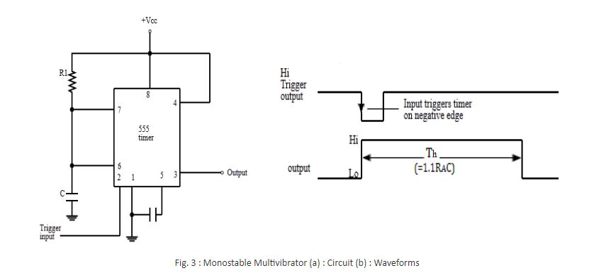
Timer IC 555 is also used as one shot or monostable operation. The circuit diagram is as shown in fig.3 Since there are many real life application where many applications needs to operate for only specific time interval for such application one shot or monostable operation is suitable. When negative going pulse is applied to pin 2 which leads to output pin 3 goes to high. The time period is given by
TH = 1.1 R1 C
The negative edge of the trigger pulse causes the internal comparator 2 trigger the flip flops leads to output high at pin 3.The voltage across capacitor rises to 2VCC/3 through supply and resistor R1. When the voltage across capacitor reaches to 2VCC/3 the internal comparator 1 triggers the flip flop from and which send the output from high to low. Fig shows the waveforms associated with the operation of the IC 555 as a monostable. The output waveform shows that the wide range from microsecond to many seconds can be possible with appropriate values of R1 and C. This flexibility of time period makes IC 555 versatile for many real life applications.